Klipper accelerometer installation (to enable input shaping)
Hey makers !
After my tutorial on how to install klipper from scratch using KIAUH, this time, I will show you how to install an accelerometer to enable the input shaper feature.
To do that, I will be using klipper reference to measure resonance :
https://www.klipper3d.org/Measuring_Resonances.html#measuring-resonances
This guide will be done for two type of accelerometers :
- ADXL345 using SPI communication
- MPU6050 using I2C communication
For both of them, the procedure is the same, except for hardware wiring and configuration.
First, you have to know that it’s impossible to use SPI or I2C bus of printer mainboard, you’ll have to use the RPI one.
So, the beginning is to refer RPI as a secondary mcu in Klipper
https://www.klipper3d.org/RPi_microcontroller.html
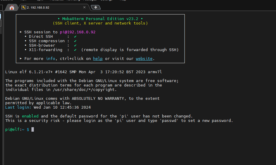
Connect to your printer’s RPI using a SSH client like MobaXTerm
Install the script by running the following commands :
cd ~/klipper/
sudo cp ./scripts/klipper-mcu.service /etc/systemd/system/
sudo systemctl enable klipper-mcu.service
Next, we have to build the micro-controller code :
cd ~/klipper/
make menuconfig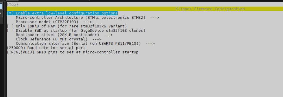
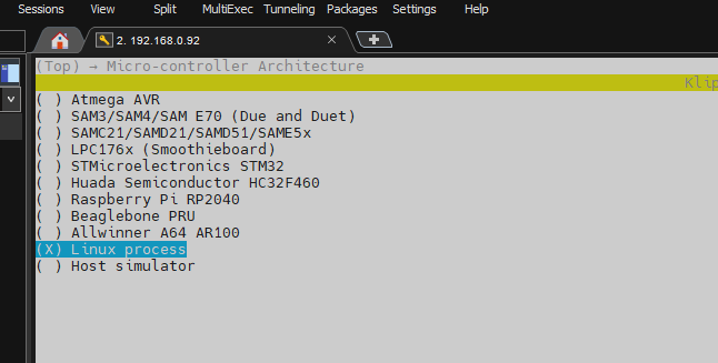
in Micro-controller Architecture section, select linux process
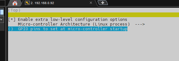
Then type Q to exit and Y to save.
We have now to install it, so run the following command to do that:
sudo service klipper stop
make flash
sudo service klipper start
If it’s not already done, you’ll have to add the current user to tty group.
My user is “pi”, so the command is :
sudo usermod -a -G tty piThere’s some more software to install to enable the input shaper feature, especially to measure resonances.
Run the following command to install dependencies
sudo apt update
sudo apt install python3-numpy python3-matplotlib libatlas-base-dev
and then numpy software
~/klippy-env/bin/pip install -v numpy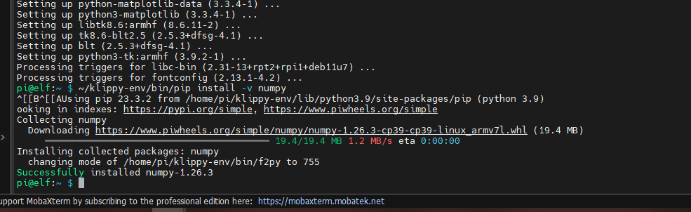
Now for the hardware installation, refer to section according to the module you will use.
Exemple : ADXL345 installer on Creativity3D Elf
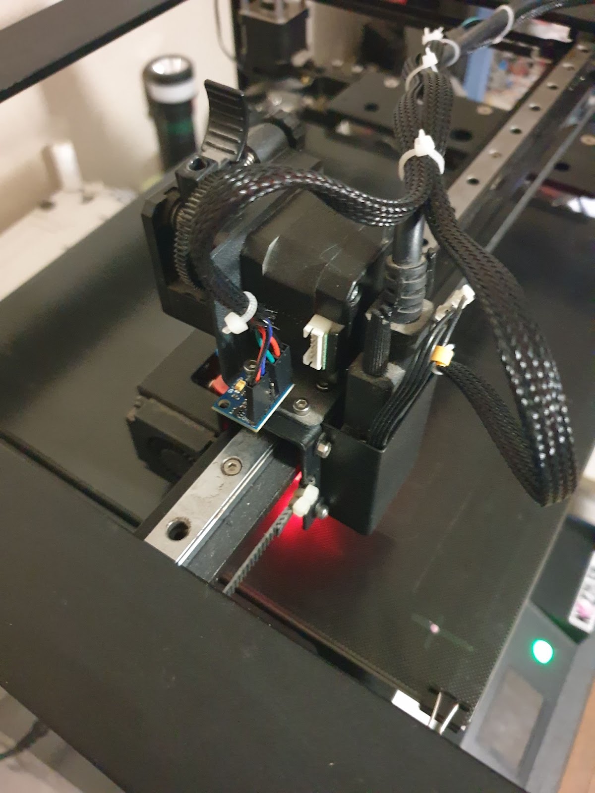
ADXL345: This accelerometer works in SPI mode.
So first, check that SPI bus of raspberry is enabled, by running the raspi-config program
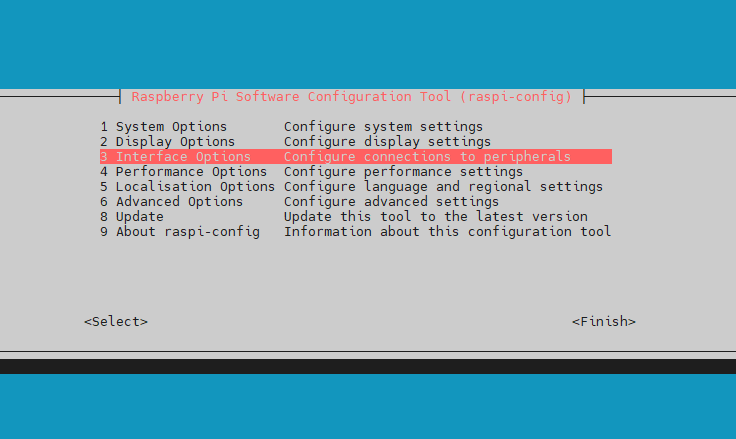
Go to interface options section and enable SPI (I4)
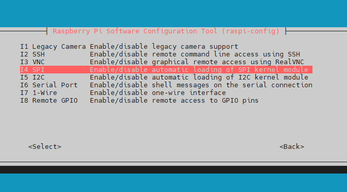
Quit raspi-config and reboot RPI.
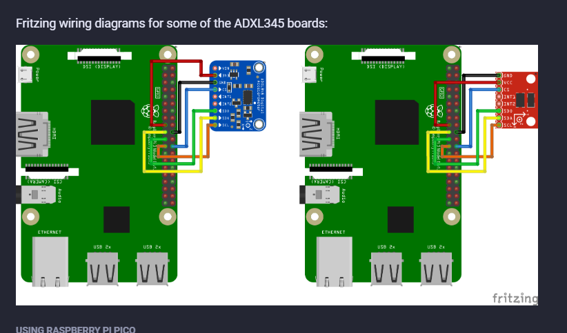
Next step is to wire ADXL345 to RPI
https://www.klipper3d.org/Measuring_Resonances.html#spi-accelerometers
Next steps will be done on Fluidd/Mainsail UI of your printer.
So, go on your printer web ui, go to configuration and open printer.cfg file.
Add reference to RPI mcu, define ADXL345 accelerometer and resonance tester
[mcu rpi]
serial: /tmp/klipper_host_mcu
[adxl345]
cs_pin: rpi:None
[resonance_tester]
accel_chip: adxl345
probe_points:
100, 100, 20 # an example
Then click on save and restart button.
For more information about the ADXL345 section, see Klipper documentation
https://www.klipper3d.org/Config_Reference.html#adxl345
MPU6050: This accelerometer works in SPI mode.
So first, check that SPI bus of raspberry is enabled by running the raspi-config program

Go to interface options section and enable SPI (I4)
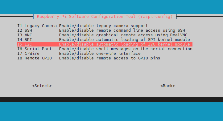
Quit raspi-config and reboot RPI.
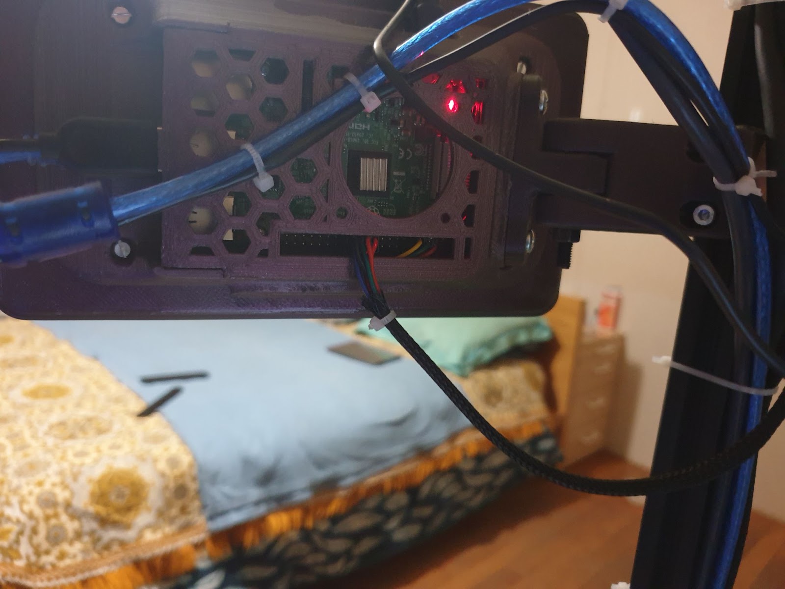
Next step is to wire MPU6050 to RPI
https://www.klipper3d.org/Measuring_Resonances.html#i2c-accelerometers
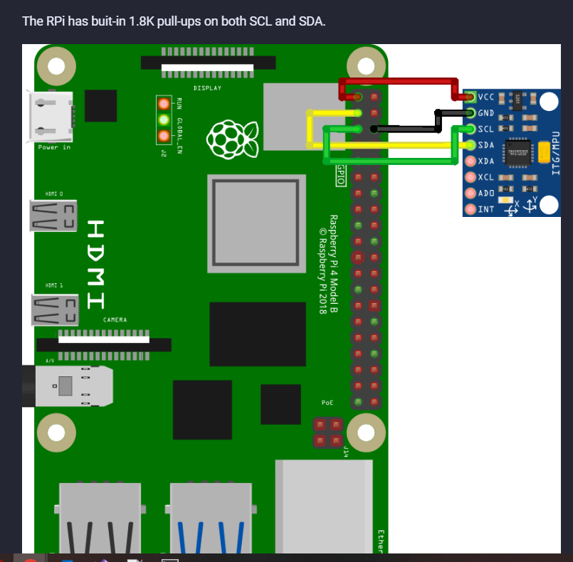
If, like me, you use an official Rasperry pi official 7’’ touch screen, this i2c bus is not available.
But don’t worry there are some more i2c bus that can be activated.
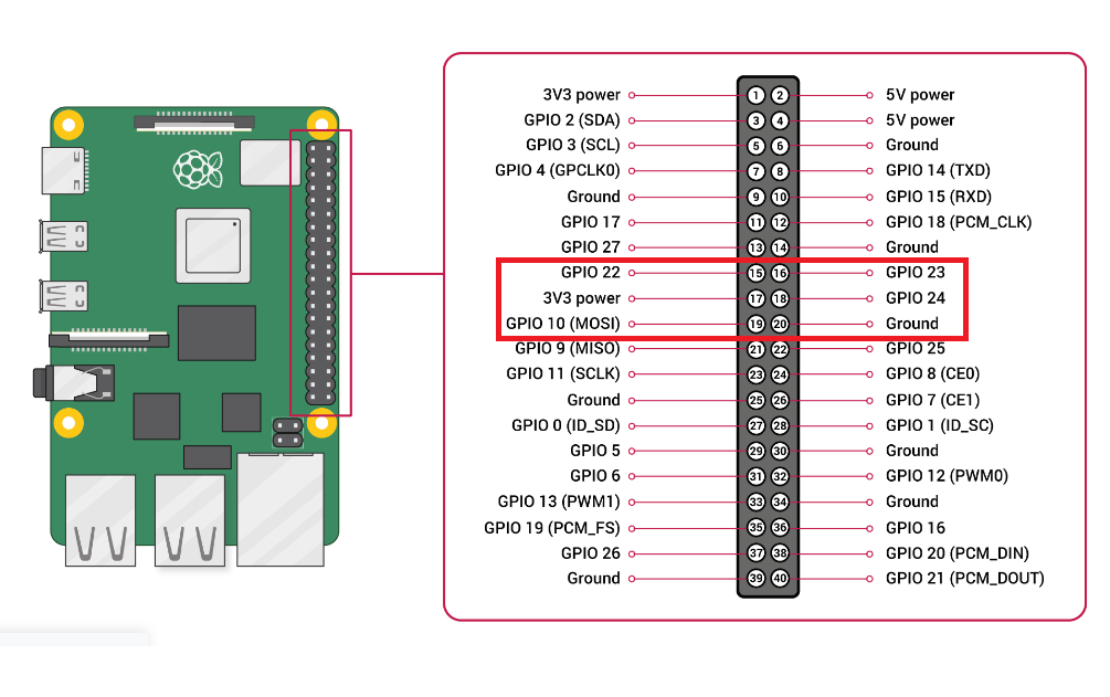
For that we will use GPIO 23 and GPIO24 and create a new i2c bus with id 4 plus the 3.3v and GND to power the MPU6050 module
To activate and configure this bus, open SSH client and edit config.txt file.
Run the following command
sudo nano /boot/config.txt
Find the line with dtparam=i2c and add below this line :
dtoverlay=i2c-gpio,bus=4,i2c_gpio_sda=23,i2c_gpio_scl=24,baudrate=400000
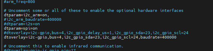
baudrate=400000 is mandatory to run communication at high speed.
Save file by done CTRL+X and reboot RPI.
When done, reconnect to printer with SSH client.
Install i2c tools by running this command :
sudo apt install i2c-toolsWhen finished, run the command :
sudo i2cdetect -y 4
If the module is correctly wired and recognized by RPI, you’ll see address 68 active.
Next steps will be done on Fluidd/Mainsail UI of your printer.
So, go on your printer web ui, go to configuration and open printer.cfg file.
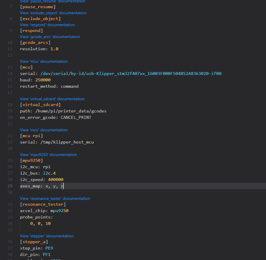
Add reference to RPI mcu, define ADXL345 accelerometer and resonance tester
[mcu rpi]
serial: /tmp/klipper_host_mcu
[mpu9250]
i2c_mcu:rpi
i2c_bus: i2c.4
i2c_speed: 400000
axes_map: x, y , z
[resonance_tester]
accel_chip: mpu9250
probe_points:
100, 100, 20 # an example
Then click on save and restart button.
For more information about the MPU9250section, see Klipper documentation
https://www.klipper3d.org/Config_Reference.html#mpu9250
Tests, Validation and activation: We have to test if all is running properly.
To check if ADXL345/MPU6050 is well wired to RPI and respond to command, Run ACCELEROMETER_QUERY command in Web UI console
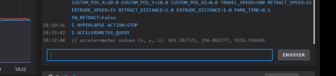
If all is working, you’ll get a response from ADXL345/MPU6050.
Time to make some Resonance Tests !!!
Run TEST_RESONANCES AXIS=X in WebUi console
And nope ! It failed…
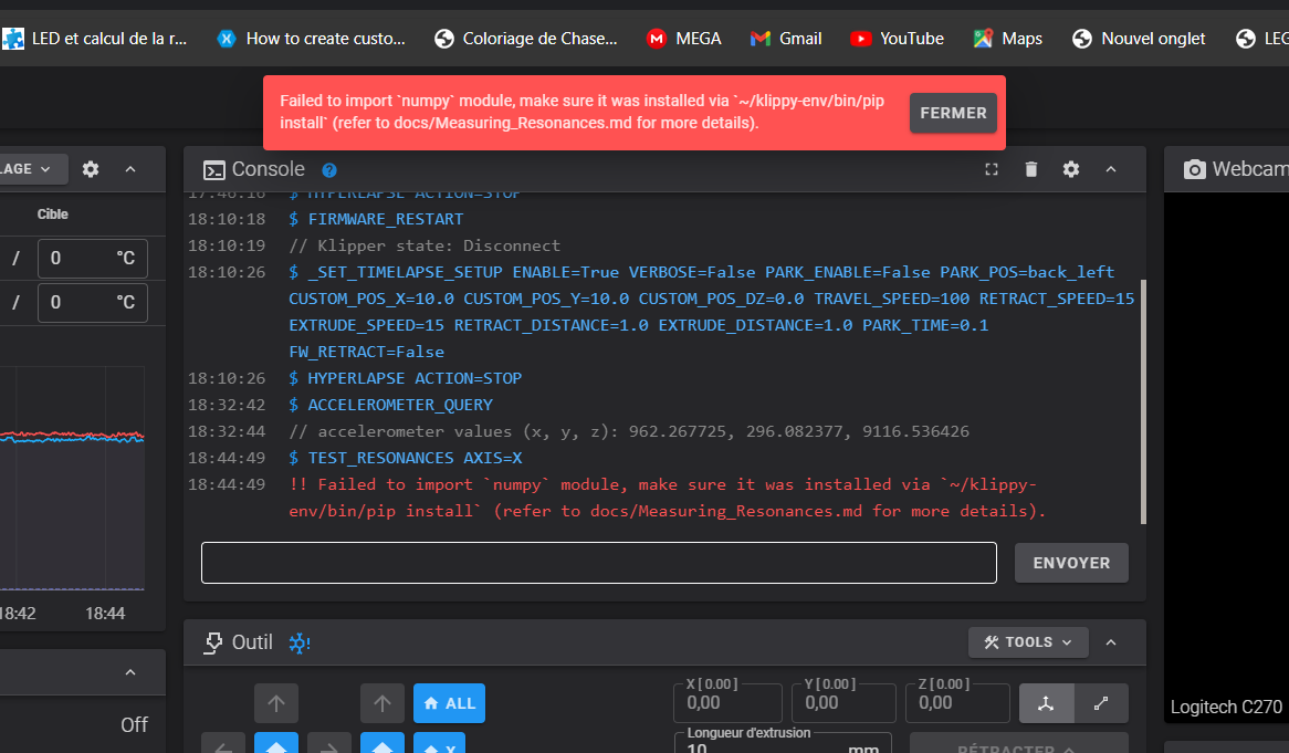
After making some research, I have found that some dependencies are missing in order to run numpy (the software used to measure resonance)
Open an SSH terminal to your printer and run :
sudo apt-get install libopenblas-base
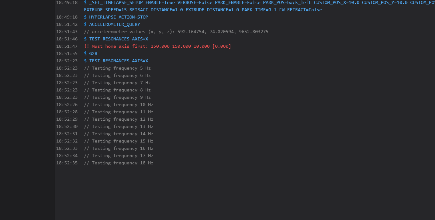
Then reboot and run again TEST_RESONANCES AXIS=X in WebUi console
Normaly it will works:
If you still got the same type of errors as before, you’ll need to install another dependency.
In SSH client and runcommand:
sudo apt-get install libopenblas-dev
Then reboot and run the test resonance command. It’ll works now.
When X axis resonance test is done, do the same on Y axis with this command :
TEST_RESONANCES AXIS=Y
Finally, 2 csv files have been generated. We will make png files from those csv with a native python script.
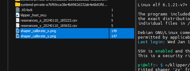
Csv files are located to /tmp/ folder in RPI.
Open SSH client to your printer and run those commands to generate png images :
~/klipper/scripts/calibrate_shaper.py /tmp/resonances_x_*.csv -o /tmp/shaper_calibrate_x.png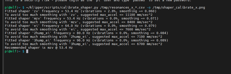
~/klipper/scripts/calibrate_shaper.py /tmp/resonances_y_*.csv -o /tmp/shaper_calibrate_y.png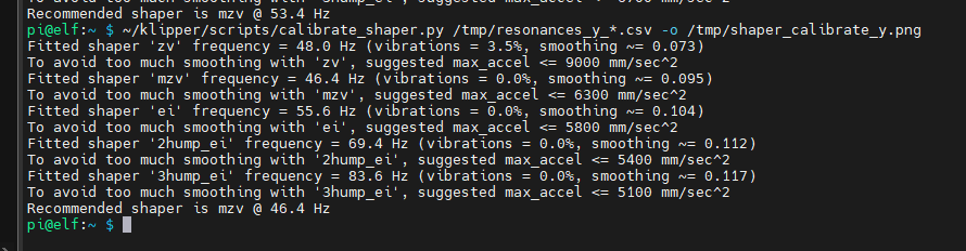
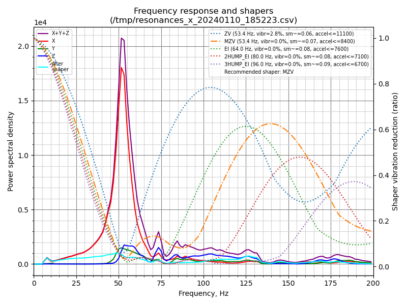
For each axis, you’ll see that RPI make some process and finally a recommendation about algorithm and value to use for input shaping.
– X axis, recommended shaper is mzv at 53.4 Hz that impose max acceleration at 8400mm/s²
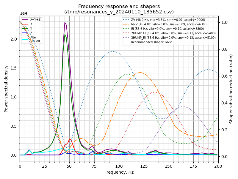
– Y axis, recommended shaper is mzv at 46.4 Hz that impose max acceleration at 6300mm/s²
In tmp folder, you’ll also find the png image generated :
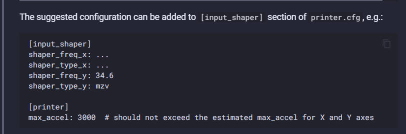
You can now manually configure input shaping section in printer.cfg with recommended values :
As far as I’m concerned, I’m not going to use this method. I prefer to use the input shaper auto calibration feature:
https://www.klipper3d.org/Measuring_Resonances.html#input-shaper-auto-calibration
For that, I just run the SHAPER_CALIBRATE command in WebUI console and let the printer do the rest.
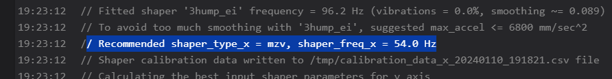
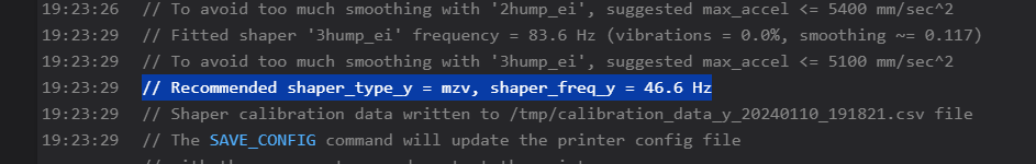
When done, you’ll have the result in console:
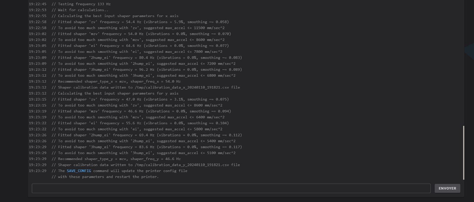
Normally, the recommended values should be around the ones calculated with RPI script:
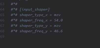
Then, run SAVE_CONFIG command in order to save values in printer.cfg
If you want to check, values are at the end of file :
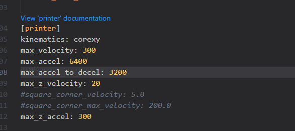
Last thing to do is to set the max_accel and max_accel_to_decel values in [printer] section according to recommended values
X axis:

Y axis

I’ll take the smaller of the two values and update the printer section.
For max_accel_to_decel value, you’ll have to divide by 2 the max_accel value
And that’s it !
Input shaping is now configured and operational for your printer.
Hint : to have the best results, place the accelerometer as close as possible to the nozzle.
Like my Klipper installation tutorial, I’ll hope you’ll find this usefull.
See you in Nozzler.io for new tests and tutorials !
De nature curieuse, je suis tombé dans l’impression 3d il y a 6ans. Depuis c’est devenu une passion étendu à la gravure/découpe laser et CNC. Passionné aussi d’informatique et de robotique, les parties firmware et technique des imprimantes 3D n’ont quasiment plus de secret pour moi.